
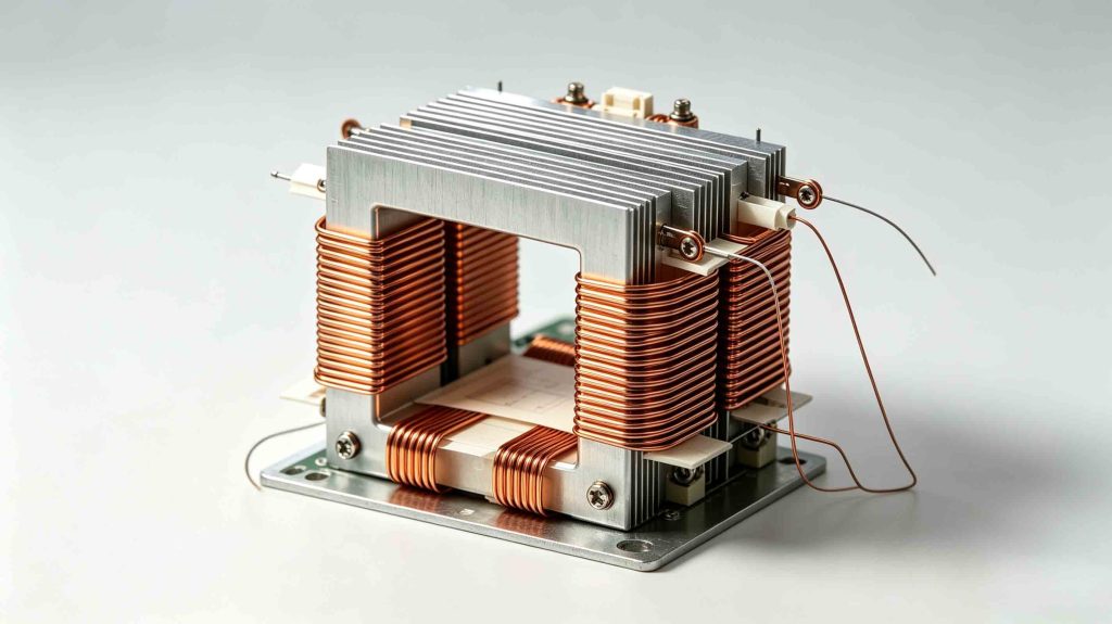
Transformer core heating is one of the most common issues affecting transformer efficiency, reliability, and service life. While transformers are designed to operate within specified temperature limits, abnormal core heating may indicate underlying problems that can lead to insulation degradation, increased losses, reduced efficiency, and even catastrophic failure if left unresolved.
This article explains the main causes of transformer core heating and the practical steps manufacturers, engineers, and operators can take to prevent it.
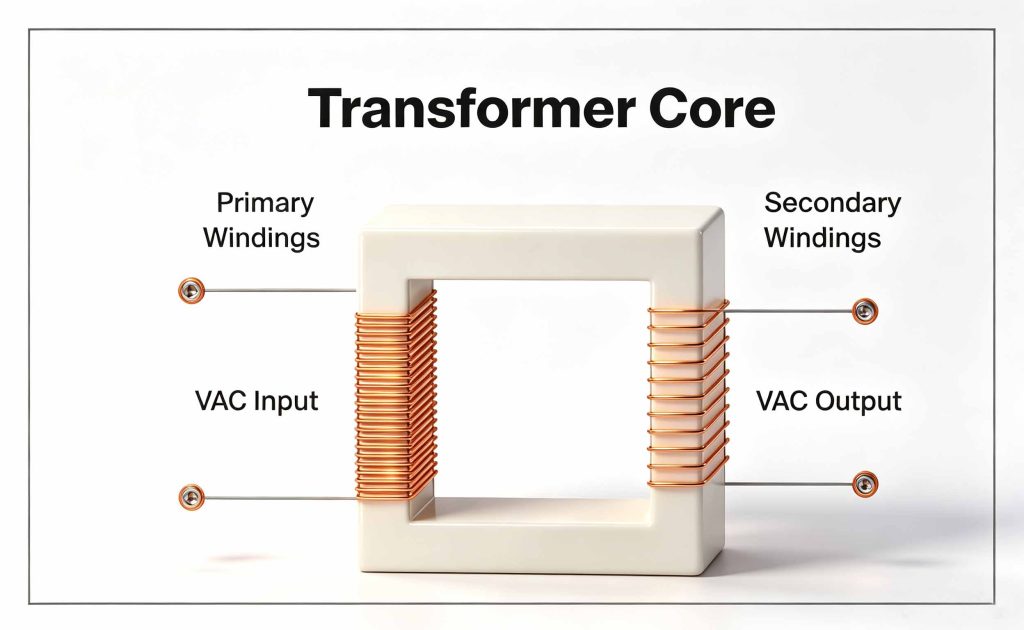
The transformer core is the magnetic pathway that channels flux between windings. Because it is made of thin, stacked silicon-steel laminations, the core is designed to minimize energy loss while carrying that flux. When something disrupts this design intent — whether a manufacturing defect, an operating condition outside normal parameters, or aging insulation — the core generates more heat than it is built to dissipate. Since the core sits at the thermal center of the transformer, excess heat there transfers directly to the windings and oil, shortening the life of the entire unit.
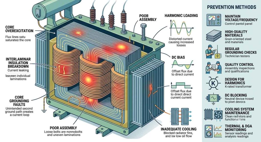
When a transformer operates above its rated voltage or below its rated frequency, magnetic flux density in the core rises above design levels. This drives the core into saturation, sharply increasing both hysteresis and eddy current losses. Overexcitation is a common concern during system disturbances, load rejection events, or when a transformer is switched in with residual flux still present.
Each steel lamination in the core is coated with a thin insulating layer to keep eddy currents confined to individual sheets. If this coating degrades — due to age, mechanical stress, or manufacturing defects — eddy currents can flow between laminations instead of staying isolated within them. This creates localized hot spots that can be difficult to detect until damage has already occurred.
A transformer core is normally grounded at a single point to safely drain static charge. If a second, unintended ground point develops — often from loose core bolts, damaged clamping structures, or foreign conductive debris — a circulating current path forms between the two grounds. This creates a continuous current loop through the core structure, generating significant and often rapidly worsening heat.
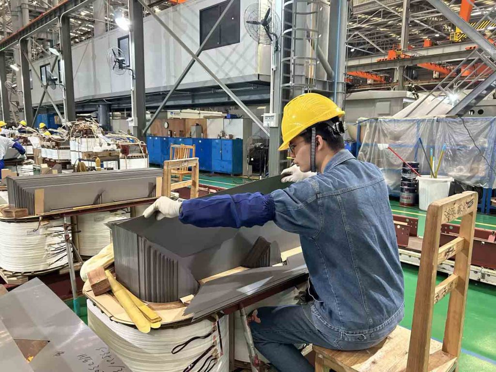
Wide or uneven laminations, burrs left from stamping, or improperly tightened core bolts all increase localized losses. During manufacturing, even small deviations in lamination stacking or insulation coating thickness can create weak points where heating concentrates over years of operation.
Modern loads — variable frequency drives, rectifiers, LED lighting systems, and other nonlinear equipment — inject harmonic currents into the power system. These harmonics increase both eddy current and hysteresis losses in the core at a rate disproportionate to their magnitude, since core losses scale with the square of frequency for eddy currents. Transformers not designed with harmonic loading in mind are especially vulnerable.
Direct current flowing into the neutral of a transformer — whether from geomagnetically induced currents (GIC) during solar storms or from half-wave rectification in nearby DC systems — biases the core’s magnetic operating point. This pushes the core toward saturation on alternating half-cycles, dramatically increasing losses and audible noise, along with heat.
Even a core operating within normal loss parameters can overheat if the cooling system — radiators, fans, or oil pumps — is undersized, clogged, or malfunctioning. Reduced oil flow or blocked radiator fins prevent heat generated in the core from being carried away efficiently, causing temperatures to climb even under normal load.
Operators should monitor the following indicators:
Abnormal temperature rise
Increasing oil temperatures
Unexpected load losses
Dissolved gas analysis abnormalities
Localized hot spots detected through thermal imaging
Unusual transformer noise or vibration
Rapid insulation aging
Early diagnosis significantly reduces maintenance costs and prevents unexpected outages.
Maintain proper voltage and frequency operation. Avoid sustained overexcitation by keeping the transformer within its rated V/Hz limits, and coordinate protection relays to trip on sustained overexcitation events.
Specify high-quality core steel and lamination insulation. Working with manufacturers who use grain-oriented silicon steel with consistent coating quality reduces the risk of interlaminar breakdown from the outset.
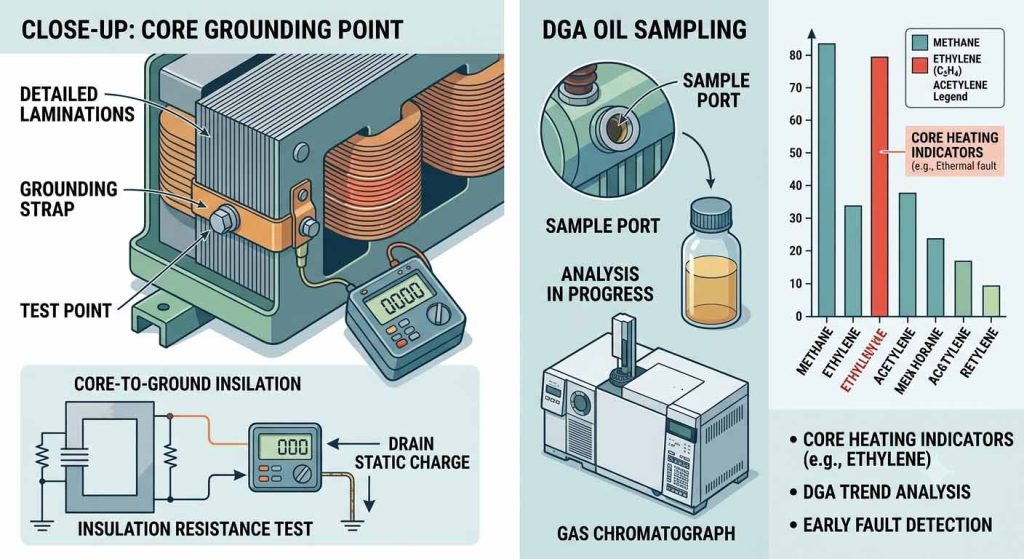
Perform regular core grounding checks. A core insulation resistance test, ideally during scheduled outages, can catch a developing second ground point before it becomes a circulating-current problem.
Follow strict manufacturing and assembly quality control. Tight tolerances on lamination stacking, bolt torque specifications, and burr-free stamping all reduce the chance of localized hot spots forming during the transformer’s operating life.
Account for harmonic loads in the design stage. If a transformer will serve nonlinear loads, specify a K-rated or harmonic-mitigating transformer design rather than retrofitting a standard unit after problems appear.
Install DC blocking or monitoring where GIC risk is significant. In regions prone to geomagnetic disturbances, neutral blocking devices or GIC monitoring systems can protect the core from sustained DC bias.
Keep the cooling system in good working order. Routine inspection of radiators, fans, and oil pumps — along with periodic oil analysis and dissolved gas analysis (DGA) — helps confirm that heat generated in the core is being properly removed and that no abnormal thermal fault is developing.
Use thermal and DGA monitoring. Continuous or periodic dissolved gas analysis is one of the most reliable ways to detect early-stage core heating, since specific gas patterns (such as elevated ethylene relative to other hydrocarbons) can point toward thermal faults in the core structure before they show up as a measurable temperature rise.
Scheduled maintenance significantly improves transformer reliability and extends service life.
Select Transformers Designed for Specific Applications
Different applications require specialized transformer designs.
For example:
Renewable energy projects require transformers capable of handling bidirectional power flow.
Industrial applications may require harmonic-resistant designs.
Data centers demand highly reliable and energy-efficient transformers.
Utility substations require robust thermal management under continuous heavy loading.
Choosing the appropriate transformer specification minimizes abnormal heating risks throughout the equipment’s operating life.
Transformer core overheating can result in:
Increased energy losses
Reduced operational efficiency
Premature insulation failure
Higher maintenance costs
Unexpected system outages
Reduced transformer lifespan
Considering that large power transformers are critical assets in modern power systems, preventive measures provide substantial long-term economic benefits.
Transformer core heating rarely comes from a single cause — it is usually the result of a combination of electrical, mechanical, and environmental factors acting over time. Understanding these root causes allows engineers and operators to catch problems early, through a mix of good design practices, quality manufacturing, and routine diagnostic testing. A transformer with a well-maintained, properly grounded, and correctly loaded core will consistently outlast one where these fundamentals are overlooked — making core thermal management one of the most cost-effective areas of preventive maintenance in the entire fleet.
Q1: What measures has Pearl Electric adopted in its transformer core manufacturing process to prevent core overheating at the source?
A: Pearl Electric exercises strict quality control over core manufacturing:
Q2: What customized solutions does Pearl Electric offer to address core heating caused by harmonics in non-linear loads (such as variable frequency drives, data centers, and PV inverters)?
A: For applications involving high harmonic content, Pearl Electric provides designs for harmonic-resistant and specialty transformers:
Q3: If core overheating caused by “multi-point grounding” occurs during transformer operation, how does Pearl Electric’s structural design facilitate rapid troubleshooting?
A: Transformer cores are designed for single-point grounding during normal operation; multi-point grounding creates a closed loop, resulting in intense circulating currents and overheating.
Q4: What are the recommended standard procedures for monitoring and routine maintenance regarding the risk of transformer core overheating?
A: Based on technical recommendations from Pearl Electric and standard O&M protocols, the following comprehensive diagnostic measures are recommended: